How to Make a Surface Plate Into a Gage
Surface plates provide a stable reference surface on a large scale, enabling multiple gage setups, but they can also be turned into a gage themselves.
#qualitygagingtips #Basics

Share
Surface plates provide a large, flat reference surface that can be extremely useful for inspecting incoming, in-process or finished parts. The surface plate is often referred to as the foundation of measurement since it provides the reference for much of the layout work done in an inspection cell. When used in combination with various gages and accessories, such as height gages, gage blocks, angle plates and squares, they can be used to check a wide range of parameters, including length, flatness, squareness, straightness, angle, feature location and runout. Surface plates are simple and extremely versatile.
Surface plates provide a stable reference surface on a large scale, making a great many gaging setups possible on a single, simple piece of equipment. When a gaging application does not warrant the purchase of a special-purpose fixture gage, surface plates can provide an economical, all-purpose solution. Surface plates also come in many sizes, making them usable for a wide range of part sizes.
Featured Content


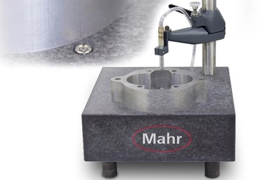
However, users may not realize that the surface plate can become a gage. A hole can be bored in the plate and a gage head installed to inspect flush surfaces for flatness without the use of a height stand. When small parts are involved, inspection can be done by simply moving a part over the probe and reading the flatness variations directly on the amplifier readout. What is happening here is that the three highest points on the surface plate are creating a plane on which the part rides. The probe mounted in the plate then senses the change or variation in the surface of the part as it is moved over it. This is a dynamic check in that the part must move to determine the out-of-flatness condition, so, rather than have an operator try to remember the highest and lowest value on the display and figure out the difference — which is the total out-of-flatness condition — the amplifier would be set to its dynamic TIR (max-min) mode, and the result would be the out-of-flatness condition.
Of course, an “assumption” must be made with this form of flatness check. Note that, in this example, there is one electronic probe the part is moved over it. Thus, there is no way that every square millimeter of the part could ever be explored. What generally happens is that the operator will follow a pattern on the part that covers the outer and inner area. The user then “assumes” everything in between is within what was measured. That is usually the case, but some areas may be missed. Nevertheless, for a fast and high-performance check, this type of flatness gage cannot be beat.
Speaking of high performance — and again this is a relative term — surface plates come in many grades, and the grade will help determine the performance of the system. Three-point support provided on a surface plate may have an accuracy to 50μ" (inspection grade A). Other plate sizes and accuracies are available. This must be considered as part of the measurement’s potential error.
To take the gage concept one step further, a second gage head mounted in an arm/stand configuration can be positioned directly above the one embedded in the surface plate, permitting independent measurements of flatness, thickness and parallelism. For relatively small parts, it is fairly easy to move the part between the probes to get readings of flatness and parallelism. The thickness check might be made either at the beginning or end of the dynamics and used as the nominal thickness, with the parallelism result applied to this. With so many things going on and the need to share probes, it becomes a little more complicated for the operator.
Sometimes the parts may be large sheets of films, plastics or metal and large-scale precision thickness measurements may be needed. Or maybe there are circuit boards where certain lands need to be verified for thickness. This is when the surface plate can act as the base of a large thickness gage. The surface plate is economical even in large sizes and a robust arm or strong bridge can be used to support the upper probe over the probe in the base. This enables the user to move the large sheets between contacts to the specified location to get the thickness measurement.
With the simple, single-probe flatness gage, watching one readout for flatness variation and remembering the min/max is not that challenging. However, even in this application, a dynamic function on the amplifier could be employed to remember these points in the background and provide the difference, which would be the flatness deviation. Or, to make it easier for the operator, especially with large parts requiring multiple measuring points, a computer-based system with a guided sequence could lead them through gathering the data in a specified order and produce a data table for the sample.
RELATED CONTENT
-
Surface Finish: A Machinist's Tool. A Design Necessity.
Simple "roughness" measurements remain useful in the increasingly stringent world of surface finish specifications. Here's a look at why surface measurement is important and how to use sophisticated portable gages to perform inspections on the shop floor.
-
Composites Machining for the F-35
Lockheed Martin’s precision machining of composite skin sections for the F-35 provides part of the reason why this plane saves money for U.S. taxpayers. That machining makes the plane compelling in ways that have led other countries to take up some of the cost. Here is a look at a high-value, highly engineered machining process for the Joint Strike Fighter aircraft.
-
Understanding Errors In Hand-Held Measuring Instruments
Different instruments (and different operators) are prone to different errors.

 (1).1676494398075.png)