What to Know About Decoding Surface Finish Gages and Parameters
Long-wavelength waviness and short-wavelength roughness require a wide variety of instruments and parameters for proper measurement — and lower numbers aren’t always better.
#Basics #qualitygagingtips

Share
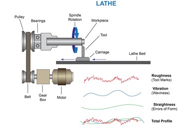
Figure 1.
We usually think of "smooth" as "slick" or "slippery." But did you know that a surface that is too smooth can be sticky? For example, racing slicks on drag cars increase traction with the pavement and in the same way, a sailboat hull that is too smooth can cause a higher degree of drag through the water. The quality or finish of a surface affects parameters such as how a part will fit and wear, reflect light, transmit heat, distribute lubrication and accept coatings.
The intended use of a finished part should determine the nature the surface. The goal is to fulfill the engineering requirements of the application without wasting time and effort on a higher than necessary finish. Therefore, when an engineer specifies the surface finish on a print, the intent is not just to make the part look good, it is functional.
Featured Content


Years ago, an experienced machinist would use a scratch pad and an educated fingernail to determine the surface quality of a part. Today, while scratch pads are still in occasional use, there are a plethora of surface finish standards, a wide array of parameters to measure surface and a robust variety of gages with which to measure it.
Every machining operation leaves marks on the surface of a part. As shown in Figure 1, surface finish — also known as profile — is composed of two components: waviness and roughness. Waviness, or longer-wavelength variation, is caused by macro-type influences like worn spindle bearings or vibration from other equipment on the shop floor. Roughness — the short-wavelength pattern of tool marks from grinding, milling or other machining processes — is influenced by the condition and quality of the tooling. The operator's choice of feed rate and depth of cut can also influence both components.
As dimensional tolerances have grown steadily tighter over the years and the need for documentation and traceability ever greater, the role of surface finish measurement in the manufacturing process has grown dramatically. In the 1940s, surface irregularities took up roughly 15% of the tolerance band. Today that proportion is frequently 50% or more.
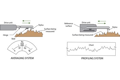
Figure 2.
What are the Types of Surface Finish Gages?
The two basic types of surface finish gage, as shown in Figure 2, reveal these measurements. These are skid-type (averaging) systems and skidless (profiling) systems.
Skidded gages have a hinged probe assembly, with the probe riding next to a relatively broad skid that also contacts the workpiece. The skid tends to filter out waviness, so the probe measures only short-wavelength variations. A skidded gage has a dial or LCD readout to display the measurement as a single numerical value.
Skidless gages use a precision internal surface as a reference, so the probe can respond to waviness as well as roughness. In order to allow separate analysis of long- and short-wavelength variations, profiling gages usually generate a chart (on paper or on a computer screen) rather than a single numerical result.
How Do You Calculate Surface Finish Parameters?
Every application reacts differently to various combinations of roughness and waviness, so the industry has responded by creating more than 100 formulae to calculate surface finish parameters from the same measurement data. Each of the parameters has its own advantages and limitations, and many are application-specific.
For most applications, no one parameter provides all the information a shop needs to define a surface. This means that a full definition requires a combination of two or three parameters. In some cases, the relationship or ratio of one parameter to another might be used as a parameter.
However, most shops are able to confine their measurements to around a half-dozen parameters, with measurements using microinch or micron units.
Ra is the most widely used parameter because it provides an arithmetic average of surface irregularities measured from a mean line that lies somewhere between the highest and lowest points on a given cut-off length.
To differentiate between "spiky" and "scratched" surfaces having the same Ra, shops should use additional parameters such as Rp (Maximum Peak Height), Rv (Maximum Valley Depth) and Ry (Maximum Peak-to-Valley Roughness Height).
If surface finish is called out on a drawing but not otherwise specified, standard practice assumes Ra. But no single parameter is best for all types of parts and many applications are best served by using two or more parameters: for example, Ra in combination with Rmax (maximum roughness) may provide a good general idea of the part's performance.
Therefore, maintaining good control over surface finish is not just a challenge, but an opportunity. In some cases, good surface control may allow you to safely reduce precision in other areas.
RELATED CONTENT
-
Properly Reading Dial Indicators
Dial indicators provide useful readings about tolerance ranges at a glance — but new users need to know how to set up these indicators before using them.
-
Predictive Maintenance And Machine Tool Calibration Techniques
Here are some of the tools and techniques for making sure machine tools stay at peak performance levels.
-
Measuring Part Geometry On The Shop Floor
Measuring workpiece dimensions is relatively simple for machine operators but measuring workpiece geometry which involves more complex comparisons of part shape to an ideal shape--is now also practical on the shop floor. The gaging equipment for doing this is coming down in price while becoming easier to use.


 (1).1676494398075.png)